Cockpit part 1
Now it starts to look like a hovercraft!
I marked out the 4 points off the plan that represent the outline of cockpit. I then used a large peice of pvc pipe to mark the curve using these points.
Once I double checked the lines were correct I glued the bottom stringers down for the cockpit and the seat.
I marked out the 4 points off the plan that represent the outline of cockpit. I then used a large peice of pvc pipe to mark the curve using these points.
Once I double checked the lines were correct I glued the bottom stringers down for the cockpit and the seat.

3 peices of ply were then glued together to form the 2 cockpit sides

The outline of the sides were marked and the ply cut. Next was to place the sides against the stringers and temporarily glue in place while the glue dried. I used rope and straps to ensure the sides were square


As the sides bent around the stringers the joins in the sides opened up so I added 10x50mm timber to each join.
Next was to attach the top stringers. This required 3 strips glued together. Having 3 peices allowed the timber to bend easily but once dry it holds its shape very well. Once again I used straps and rope to hold square. Many clamps were required.
Next was to attach the top stringers. This required 3 strips glued together. Having 3 peices allowed the timber to bend easily but once dry it holds its shape very well. Once again I used straps and rope to hold square. Many clamps were required.


Next was to design the dashboard. The plans are not very clear here so I just went off the plan for this. I chose a dash height of 150mm to allow enough room for engine gauges etc.


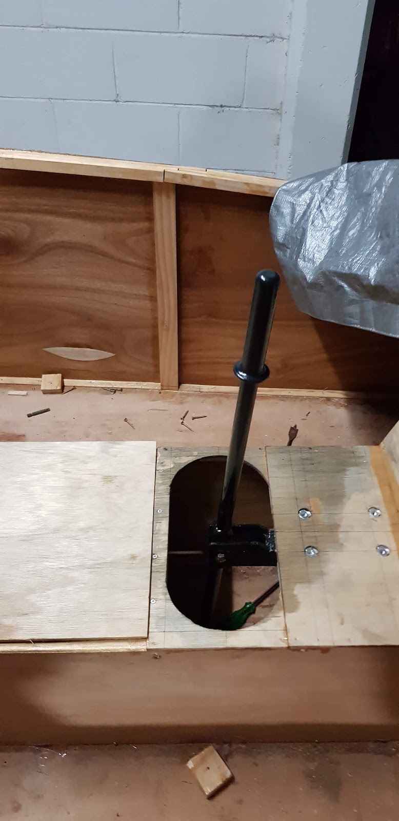
I marked up the location of the joystick and installed ply around it's full movement.
Next was to glue ply in place near the lift duct. The plans are not clear here so I just went with what looked correct. I will fill in with foam and shape to make the inlet lip.


Here is the joystick


Comments
Post a Comment